PPT On Optical Networking

Published in: Networking
3,403 views
  • M

    Muhammad R

    • Dubai
    • 4 Years of Experience
    • Qualification: Bachelor of Science, CCNA Certified, Nebosh Certified, Flash...
    • Teaches: Computer, Maths, Science, Computer science, Mathem...
  • Contact this tutor

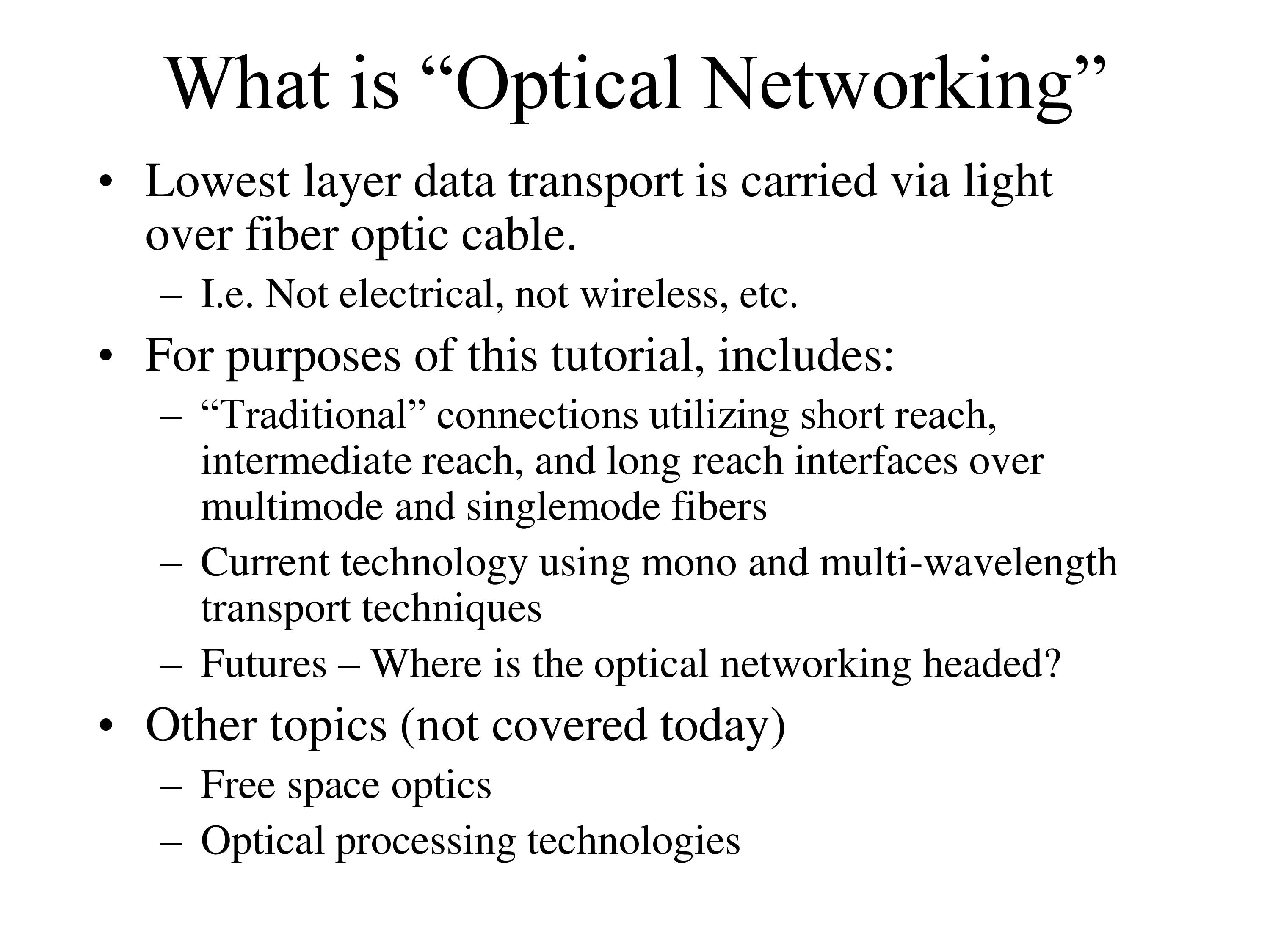
An optical network is a type of data communication network built with optical fiber technology. It utilizes optical fiber cables as the primary communication medium for converting data and passing data as light pulses between sender and receiver nodes.This PPT will give a complete knowledge about Optical Networking.

  • 1
    Optical Networking Basic Engineering, Architectures, and Strategies, (Take 2)
  • 2
    WARNING! ! ! Do not gaze into fiber with remaining eye!
  • 3
    Purpose ' Develop a basic familiarity with engineering design issues associated with emerging optical network technologies ' Communicate architectural and non- technical aspects of developing such infrastructure
  • 4
    Outline Definition of scope For purpose of this tutorial: What is optical networking? Fiber characteristics How does fiber affect the network? Optical components and systems architectures Basic building blocks and how they fit together Case studies Supercomputing 2002 WAN engineering NCREN optical engineering Informational Sources How to stay in the thick of it
  • 5
    What is "Optical Networking" Lowest layer data transport is carried via light over fiber optic cable. I.e. Not electrical, not wireless, etc. For purposes of this tutorial, includes: "Traditional" connections utilizing short reach, intermediate reach, and long reach interfaces over multimode and singlemode fibers Current technology using mono and multi-wavelength transport techniques Futures — Where is the optical networking headed? Other topics (not covered today) Free space optics Optical processing technologies
  • 6
    Pieces Whats on the "ends" — Optical transmission sources Characteristics — laser frequency, spectral width, modulation — Receivers Whats in the "middle" - Fiber Optical characteristics and implications for network performance
  • 7
    Why are fibers what they are? Most data communications fibers are silica based Fibers are "pretty clear", but not perfectly clear Impurities and construction limitations will constrain the optical transmission properties Many or the design properties of fibers are based on inherent technology capabilities/limitations of the light sources available at the time LED sources were good for multimode fibers in the 850 nm range Higher speed lasers at 1310 nm required lower attenuation and dispersion in the fiber — and vice versa Higher data rates required still further evolution into the 1550 nm range
  • 8
    So whats up wit the fiber? Fibers are "light guides" Almost clear, silica based Use materials of different refractive indices to confine and guide the light , Core Lowest refractive index Primary light medium Cladding Higher index of refraction than core Bends escaping light back into core , Jacket Mechanically protects the fiber
  • 9
    Limiting factors of optical fiber Junctions Splices Connectors Linear effects — directly related to the length Attenuation Absorption Scattering Dispersion ' Modal dispersion Chromatic dispersion ' Polarization Mode dispersion
  • 10
    Limiting Characteristics of Fiber Linear effects — a function of the fiber length Attenuation — reduces power output of a fiber segment Absorption — light is absorbed due to chemical properties of the fiber so that less energy is emitted ' Scattering — light is re-directed by the molecular properties of the fiber resulting in leakage into the cladding, jacket, or lost at junctions Dispersion — broadens the optical pulse over length of a fiber segment Modal — differing "modes" traverse different paths in the fiber Chromatic — different frequencies of light travel at different speeds in a medium Polarization — orthogonal light waves travel at different speeds in the fiber
  • 11
    Limiting Characteristics of Fiber Non-Linear effects — Self phase modulation — Four wave mixing — Ramon scattering
  • 12
    Review of basic architecture: Laser emits a light source X Modulator "blocks" X according to electrical bit stream (Intensity Modulation) Direct modulations of laser typical in lower data rates External mod more common in high speed data rates Receiver regenerates electrical bit stream from modulated optical signal Laser Modulator _____.A................-.N Receiver Fiber Connector Connector
  • 13
    The "Eye" Diagram The analog representation of the digital signal waveform — Overlays both "0" and "l" values Rise/ Fall Power Hold Logic "l" Logic "0" Time
  • 14
    Optical characteristics of fiber ' Low attenuation in 1310 nm range Low dispersion in the 1550 nm range 1550nm 131 Onm
  • 15
    1550nm Low-Loss Wavelength 1 10 -10 1250 1300nm 1550n window 1350 1450 1550 1650 Wavelength (nm) At 1550nm, wide region of low-loss wavelengths Is irresistable for WDM systems even with high dispersion. (Courtesy Celion Networks)
  • 16
    Conventional Single-Mode Fiber 30 S o (0 20 10 -10 -20 -30 1250 D(1530-1565nm) = 16 - 19 ps/nm*km AD = 0.065 ps/nm2km eff = 85 um2 A 1350 1450 1550 1650 Wavelength (nm) First single-channel systems operated at 1310nm (good laser materials) W DM systems moved to 1550nm: wider loss-window, but higher dispersion Disp.-Limit = 1000 km at 2.5Gb/s in SMF, so not really a problem (Courtesy Celion Networks)
  • 17
    Dispersion-Shifted Fiber —Oops ! 10 -10 1250 1350 1450 1550 Wavelength (nm) 1650 DSF: Zero dispersion at 1550nm, so no compensation required. However, FWM severely limits optical power levels. Substantial amounts in some U.S. networks. Small Effective Core Area, So very nonlinear (Courtesy Celion Networks)
  • 18
    NZ-DSF L-Band o S-Band 20 16 12 8 4 -4 1510 SMF-28 DSF 1530 C-Band 1550 1570 1590 1610 Wavelength (nm) TrueWave Classic TrueWave Reduced Slope E-LEAF Move dispersion zero outside bands of interest Various types available Increased effective core area to equal SMF (Courtesy Celion Networks)
  • 19
    Attenuation Absorption — Chemical properties of the fiber absorb some of the energy Scattering — Molecular properties cause the light to be re- directed — portions of it are lost in the cladding or are reflected back to the source
  • 20
    Dispersion Dispersion causes the digital waveform to be "smeared" — Rise/fall time expands over the length of the fiber Modal dispersion only present in multi- mode fibers Chromatic dispersion arises from spectral width
  • 21
    Modal dispersion ' Each "mode" travels along a different path. — Light enters the guide from different insertion angles — Each path has a different length and so arrives at different times ' Primary limiting factor of multi-mode fiber for high speed communications
  • 22
    Modal Dispersion Multimode fibers have a core diameter of 50 microns to 62.5 microns — Less rigorous tolerances make construction easier Splicing and connectors are more easily engineered Typically under 2 kilometer distances (less at high data rates) By sizing the diameter of the core properly as a function of wavelength and refractive indices of core and cladding, the wave guide can be constrained to carry only a single "mode" of the incident laser signal. Single mode fiber has a core diameter of approximately 8-11 microns SM fiber does not exhibit modal dispersion
  • 23
    Chromatic Dispersion Lasers do not emit a single wavelength — Spectral width Different wavelengths of light travel at different velocities in a given medium. — Index of refraction Tails of the laser spectral distribution travel at different speeds down the wave guide Frequency domain
  • 24
    Chromatic Dispersion Chromatic dispersion is sum of wave-guide dispersion (+) and material dispersion (-) Fiber design can vary the amount of wave-guide dispersion in order to cancel the material dispersion at a desired wavelength Zero Dispersion-Shifted Fiber (ZDSF) Non-linear effects are dampened by dispersion, so... Shift the zero dispersion point a bit past the operating wavelengths.. Non-zero Dispersion Shifted Fiber (NZ-DSF) Dispersion can be positive or negative Negative dispersion fiber can counter effects of normal fiber... Dispersion Compensating Fiber (DCF)
  • 25
    Chromatic Dispersion Measured in ps/(nm*km) E.g. 5ps/(nanometer kilometer) How would chromatic dispersion affect an OC48 link with laser at +/-lnm spectral line over a 20 km NZ-DSF fiber link? Bit period = 416ps 2 nm spectral band * 5 ps/(nm km) * 20 km = 200 ps Result: rise/fall time is 50% of bit period — The link is on the edge (may see excessive bit errors) Possible adjustments: Reduce span (add a regen point) .Find an interface with better source laser, better receiver parameters, or both — I.e. may mean a more expensive XL interface Reduce the link bandwidth — GigEthernet would likely work comfortably. OC192 with a .2 nm spectral width over 50 km Bit = 104 ps .2 nm spectral band * 4ps/nmkm * 50 km = 40 ps (+/- 20 ps) 40% of duty cycle — will probably work The finer the laser line, the less chromatic dispersion affects the emitted signal.
  • 26
    Polarization Mode Dispersion 'Single mode" fiber actually allows light consisting of orthogonal poloraizations (the electric and magnetic fields of different photons are not aligned.) "Bimodal" fiber. .. Due to construction methods, installation, environmental conditions, etc., the effective area of the core varies along the axis of the fiber. This variance if EA causes subtle differences in propagation speed of the light wave based upon the polarization of the component photons. Result: Dispersion Not well understood Typically only of concern at data rate in excess of 2.4 Gbs Measured in ps/sqrt(km) Of most concern in fiber manufactured and installed prior to early 1990s.
  • 27
    Optical Networking Components Optical Multiplexor Optical Demultiplexor
  • 28
    Optical Network Components Splitters Splits off some portion of the optical signal Splitters do not demultiplex the optical signals 100% Wavelength Converters Often require electrical intermediate step New devices allow conversion in optical domain
  • 29
    Opto-electronic Conversion Wavelength conversion is typically required to interface traditional optical interfaces to ITU "grid compliant" wavelengths used in DWDM systems CPE typically at 1310nm with relatively broad spectral band Optical Channel Modules (OCM) take the 1310 optical signal, convert it to its electrical equivalent, and then re-transmit it with the assigned ITU wavelength This is generally referred to as O-E-O This OEO process can be employed mid-span to perform some or all of the 3Rs — Retiming, Reshaping, Re- generation.
  • 30
    The Three "R"s Re-timing Verify and compensate for clocking drift Re-shaping Compensate for attenuation and/or dispersion Sharpen the "eye' Re-transmission Completely decode and re-create the digital bit stream. Often includes intelligent processing of the framing headers for O&M purposes.
  • 31
    Simple Two X Example 1310 Router A 1310 Router B Mux 1550 Dmux 1310 Router C 1550 Router D Wavelength Converter 1310 nm ->1550 nm Note: Wavelength conversion back to 1310 at Router D is not necessary because the optical receiver is actually sensitive to a broad range of optical wavelengths — including 1550.
  • 32
    Optical Add/Drop Multiplexor ' Two fiber example ' Possibly from a ring configuration Mux Dmu Dmux OADM Mux Channel Modules
  • 33
    Building the ARL OC48 for sc02 Provision OC48c Sonet wave from Army Research Lab (White oak, MD) to Supercomputing 2002 at the Baltimore Convention Center Segments: 11 km Truewave(RS) from ARL to CLPK MAX Lambda from CLPK to DCNE (Qwest pop) SC02 Lambda from ECK to BCC (via MAR) SMF from BCC(noc) to booth
  • 34
    Building the ARL OC48 for SC02 West:Frien€L9hip 25 87 Pine.Or.char.d 23 Columbia 046 20513 12 10 56 60 21794 Glenwo d 21738 Glenelg 37 Dayton 036 381 38 Dund .ssex Back River 9 39.40 Ilorth Point 21042 2 51 Ellicott City 210 Jonestown Catonsville 12Bc 2 52 11 imore •3 7 attimore Hi 3 iilge 2 090 Hanover hlands 8 Brooklyn Park 5 •A' undel Village •sville ove 20 tt Park 35 21029 20777 Briti low Clarkfiill Highland Futton 4 41 5 5 Linthicum Hei0htS Ferndale 1 2122 Brookeville Simpsonville 38 Scaggsville 20723 4 1076 Junction Furnace Br anch Glen Burnie Olney Ilorbeck 9 Sandy 1101 wo Spenc pring 21240 Harmans Severn 21144 Marley 20 r ville 09 5 olesville o. iite odmoor 3B Adelphi koma Park Chillum Burtonsville 33 33 20707 Bettsville 5 ollywood 3 Laur el Savage 20 13 Waterloo Jessu Annapoli 207 5 Bowie Ft•George G Meade Odenton 13 13 15 12 12 10 15 108 Rivier a Gr een'Have Jaco 43 each sville
  • 35
    Before NOC CPE 11 km TW(rs) CPE CPE CLPK 19 km AW DCNE 5 km AR 50 km ECK
  • 36
    Calculating Network Limits Building the ARL OC48 for SC02 CLPK (Univ. of Md) Connectors (Patch panels, interface connections, etc) = .5dB Tx = -3 dBm Rx = -28 dbM POSISMF ZD=1310, .32dB/km a) OC48 interfaces 1=1310 nm, AX =20nm 11 km Truewave RS Army Research Lab
  • 37
    Tx = -3 dBm Rx = -28 dBm 11 km tw(rs) Attenuation= .25 dbm/km Dispersion —5ps/nmkm @1550...but —8ps/nmkm @ 1310 OC48 interfaces 1=1310 nm, AX = 20nm Link Budget = -3 - (-28) = 25dBm Attenuation = u fiber connectors = (6 * -.5dB) + (Ilkm * -.25db) - -3dB - 2.75 dB = -5.75 dB Power is fine! Dispersion: At = sqrt( At2 + At2 chromatic polarization = -8ps/nm.km * 11 km * 20 nm + 0 = -1760 ps not good (given a 400 ps bit period) So how do we correct it?
  • 38
    Building the ARL OC48 for sc02 Situation: @ 1310 (or at 1550) power is good, but... At 1310 dispersion, 1760 ps, is too high to support Options: Reduce bandwidth: OC3 duty cycle is 6400 ps and would work fine — but not adequate for application Find a long reach interface, hopefully with a SW less than 2nm and at 1550
  • 39
    After Add inverted transponder! < 1 km NOC CPE 11 km Line CP Inve ed Transponder CPE CPE CLPK 19 km DCNE 5 km AR 50 km ECK
  • 40
    Tx = -3 dBm Rx = -28 dBm 11 km tw(rs) Attenuation= .25 dbm/km Dispersion —5ps/nmkm @1550...but —8ps/nmkm @ 1310 OC48 interfaces 1=1550 nm, AX = .2 nm Link Budget = -3 - (-28) = 25dBm Attenuation = u fiber connectors = (6 * -.5dB) + (Ilkm * -.25db) - -3dB - 2.75 dB = -5.75 dB Power is still fine! Dispersion: At = sqrt( At2 + At2 chromatic polarization = 5 ps/nm.km * 11 km * 0.2 nm + 0 Dispersion is no longer a problem — = 11 ps in fact would be fine for OC192
  • 41
    Why does the Inverted Transponder solve the problem? The transponder has broadband receiver(s) on both the line side and CPE side The CPE xmit was 1550 with broadband recv. By inverting the transponder we send a 1550 signal with a very narrow SW towards the CPE — dispersion is reduced
  • 42
    MAX Fiber Engineering Needed POPs in several locations Spoke to Carriers in those locations Looked at available fiber routes Discussed available fiber types Iteratively identified a set of specifc locations ' Contracted for fiber Tried to move quickly — needed the capacity urgently Contract based upon a relatively short 3 yr lease
  • 43
    MAX Primary Ring Details Two strands Lucent All Wave ' Four points of presence 49 miles total circumference Provisioning Trade-offs Where/when are additional lamdas useful ' Layer 3 protection between routers ' Backhaul access circuits to routers "PVN"s - Parallel Virtual Networks E.g. IPv6, transient applications ' Non-L3 service — e.g. NGIX access Routers are more expensive than switches Lambdas cost —$75,000 incremental cost ' But have ammortized cost of fiber, wdm nodes, support, sparing, etc that need to be included ' Hard laser wavelengths limit re-application of OCMs.
  • 44
    Fiber Engineering Specs 44.7 km -14 dB DCGW 9.8 km -2.25 dB CLPK 17 km -4 dB DCNE 20 km -5 dB ARLG
  • 45
    MAX Lambda Provisioning CLPK NGIX DCGW = ITU 33 = ITU 35 = ITU 37 X 4 = ITU 39 = ITU 33 = ITU 35 ABIL DCNE IP (oc48 sonet) GigE NGIX (oc12 atm/sonet) ARLG

Need a Tutor or Coaching Class?

Post an enquiry and get instant responses from qualified and experienced tutors.

Post Requirement

Related PPTs